What is PLC?
What is PLC? The Unseen Brains Revolutionizing Modern Industry
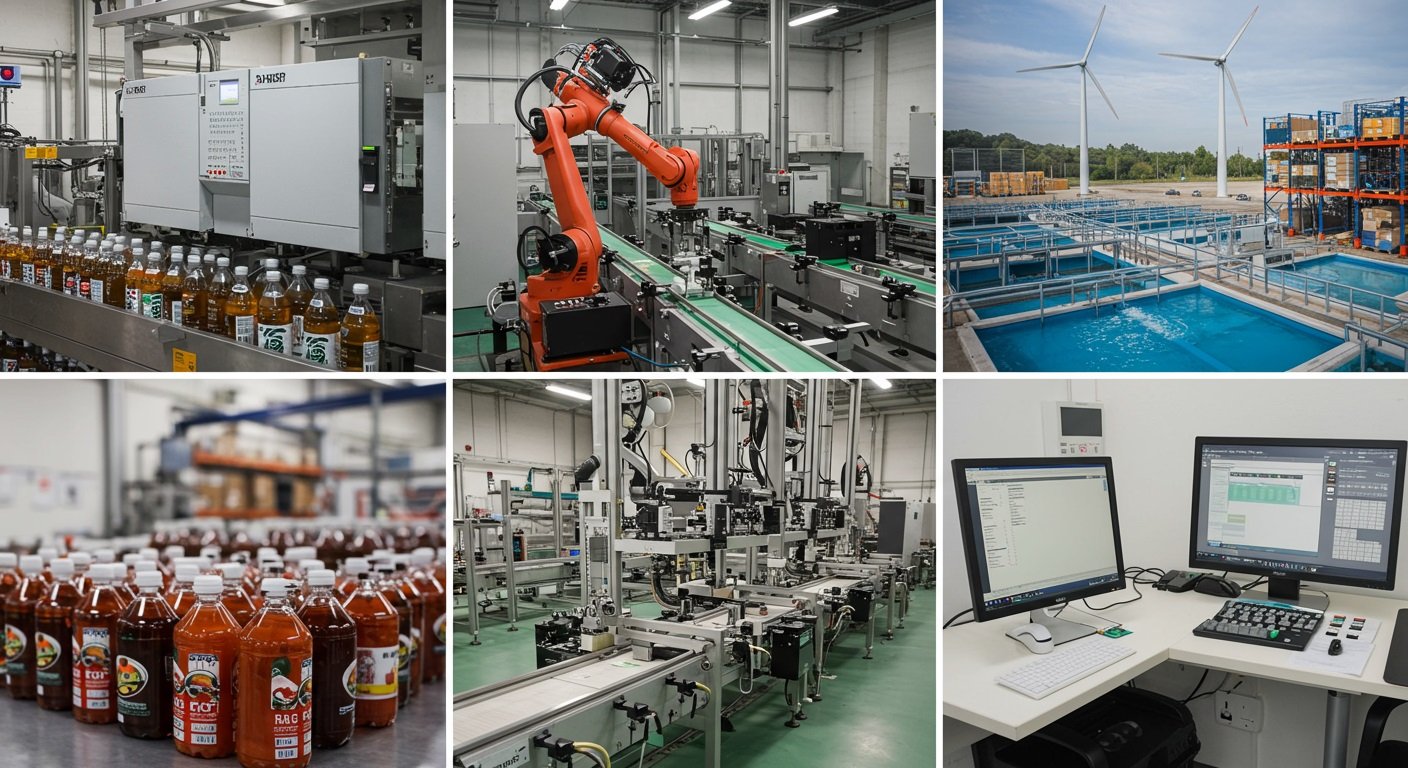
![[Image: A dynamic collage showcasing various industrial settings – a robotic arm, a complex conveyor system, a brightly lit control room panel – subtly hinting at the PLCs working behind the scenes.]](https://lh7-rt.googleusercontent.com/docsz/AD_4nXdmiRPh-4fDbdBr0IDTLYPmTA4Meik8pbFaQWvExmsf_RH8LixdCZK4_18aBsWiakToQRjV18n1IofpEnGhI9JmmEMiO6aMhWyhVVX_cwwlq8boCdzfTT0AHOGXprHdW58xtP6F?key=thqV8XyW7_CRaxBL5v0aqQ)
Ever marveled at the seamless operation of a vast car manufacturing plant, where robotic arms weld with precision and conveyor belts move components flawlessly? Or perhaps you’ve wondered how a city’s water treatment facility maintains perfect chemical balances, or how your favorite beverage is bottled and packaged with such consistent quality and speed? The silent, unseen hero behind these marvels of modern industry, and countless others, is often a rugged little box of electronics known as a Programmable Logic Controller, or PLC.
In a world increasingly reliant on automation, PLCs are the workhorses, the digital brains that make complex industrial processes not just possible, but efficient, reliable, and scalable. They are the linchpin connecting the physical world of machines, sensors, and actuators to the logical world of programmed instructions.
But what exactly is a PLC? Why did it replace older technologies? How does it work its magic? And where is this ubiquitous technology heading? This comprehensive guide will demystify the Programmable Logic Controller, taking you from its fundamental concepts to its advanced applications and future potential. Whether you’re an aspiring engineer, a curious hobbyist, or a business leader looking to understand the backbone of modern automation, prepare to delve into the fascinating world of PLCs.
The Pre-PLC Era: A Tangled Web of Relays
To truly appreciate the revolutionary impact of the PLC, we must first journey back to a time before its invention – the era of relay logic control.
![[Image: A complex, old-fashioned industrial control panel filled with rows upon rows of electromechanical relays, festooned with tangled wires. Caption: "A typical relay logic control panel – complex, inflexible, and a maintenance nightmare."]](https://lh7-rt.googleusercontent.com/docsz/AD_4nXcoepg7u4_BZyJ8RQNUOq_2QUTWt2NLjId04XOZ-e9zwqnMScAqI-d9XQ9-FJOctrrLpehgr70xEgx2RPw8jSU9FRfVdhAPPZ8wk2jSX8kRLLcG__s56-SYwsbNMQpYS79FmaX60g?key=thqV8XyW7_CRaxBL5v0aqQ)
In the mid-20th century, industrial automation was primarily achieved using electromechanical relays, timers, and counters. These devices, wired together in intricate configurations, formed the control logic for machinery.
- Relays: These are electrically operated switches. When a coil in the relay is energized, it creates a magnetic field that pulls a set of contacts open or closed, thereby controlling another circuit.
- Control Systems: To create a sequence of operations (e.g., “if sensor A is ON and sensor B is OFF, then start motor C”), engineers would physically wire numerous relays together. The logic was hard-wired.
The Drawbacks of Relay Logic:
While functional, relay-based systems had significant limitations, especially as industrial processes grew more complex:
- Complexity and Size: Even moderately complex systems required hundreds, sometimes thousands, of relays. This resulted in enormous control panels, consuming vast amounts of factory floor space. The wiring itself was a spaghetti-like maze, making installation a monumental task.
- Inflexibility: If the control logic needed to be changed – even slightly – it meant physically rewiring the panel. This was time-consuming, error-prone, and led to significant production downtime.
- Reliability Issues: Relays are mechanical devices with moving parts. They were susceptible to wear and tear, contact sticking, coil burnout, and environmental factors like dust and vibration. Troubleshooting was a painstaking process of checking individual relays and connections.
- High Power Consumption: Each relay coil consumed power, leading to high overall energy usage for large systems.
- Cost: While individual relays weren’t overly expensive, the sheer number required, coupled with the extensive labor for wiring, documentation, and maintenance, made these systems costly in the long run.
- Limited Functionality: Advanced functions like mathematical calculations, data logging, or communication with other systems were extremely difficult or impossible to implement with relay logic alone.
The automotive industry, with its constantly evolving assembly lines and demand for faster model changes, was particularly burdened by these limitations. Every model year change often necessitated a complete and costly overhaul of the control panels. This pressing need for a more flexible, reliable, and easily modifiable control system set the stage for a revolution.
The Dawn of a New Era: Defining the PLC
The pivotal moment arrived in 1968. General Motors’ Hydramatic division (the automatic transmission division) issued a request for a proposal for an “electronic replacement for hard-wired relay systems.” They sought a solution that was:
- Easily programmable and reprogrammable.
- Designed to survive harsh industrial environments.
- Cost-competitive with relay systems.
- Modular and expandable.
- Simple to maintain and troubleshoot.
Bedford Associates, a company founded by Richard “Dick” Morley, responded to this challenge. Morley is widely considered the “father of the PLC” for his work on the first practical PLC, the Modicon 084 (Modicon standing for MOdular DIgital CONtroller, and 084 being Bedford Associates’ 84th project).
So, what is a Programmable Logic Controller (PLC)?
The National Electrical Manufacturers Association (NEMA) defines a PLC as:
“A digitally operating electronic apparatus which uses a programmable memory for the internal storage of instructions for implementing specific functions such as logic, sequencing, timing, counting, and arithmetic to control through digital or analog input/output modules various types of machines or processes.”
In simpler terms:
A PLC is a ruggedized industrial computer designed to automate electromechanical processes. It continuously monitors the state of input devices (like sensors and switches), makes decisions based on a custom program stored in its memory, and controls the state of output devices (like motors, solenoids, and lights).
Think of a PLC as the specialized brain of an automated system. It takes in information from its “senses” (inputs), processes that information according to pre-programmed rules, and then directs its “muscles” (outputs) to perform actions.
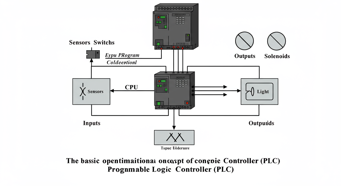 PLC (CPU, Memory, Program) -> Outputs (Motors, Lights, Solenoids). Caption: “The basic operational concept of a PLC.”] Unlike general-purpose computers, PLCs are:
- Industrially Hardened: Built to withstand extreme temperatures, humidity, dust, vibration, and electrical noise common in factory environments.
- Real-Time Operating: They must respond to changes in inputs and execute control logic within milliseconds to ensure timely and safe operation of machinery.
- Easily Programmable: Often using intuitive, graphically-based programming languages like Ladder Logic, which mimics the appearance of relay logic diagrams, making it easier for electricians and technicians to adopt.
- Modular and Flexible: Many PLCs allow for the addition or removal of Input/Output (I/O) modules to suit the specific needs of an application.
Anatomy of a PLC: Peeking Inside the Box
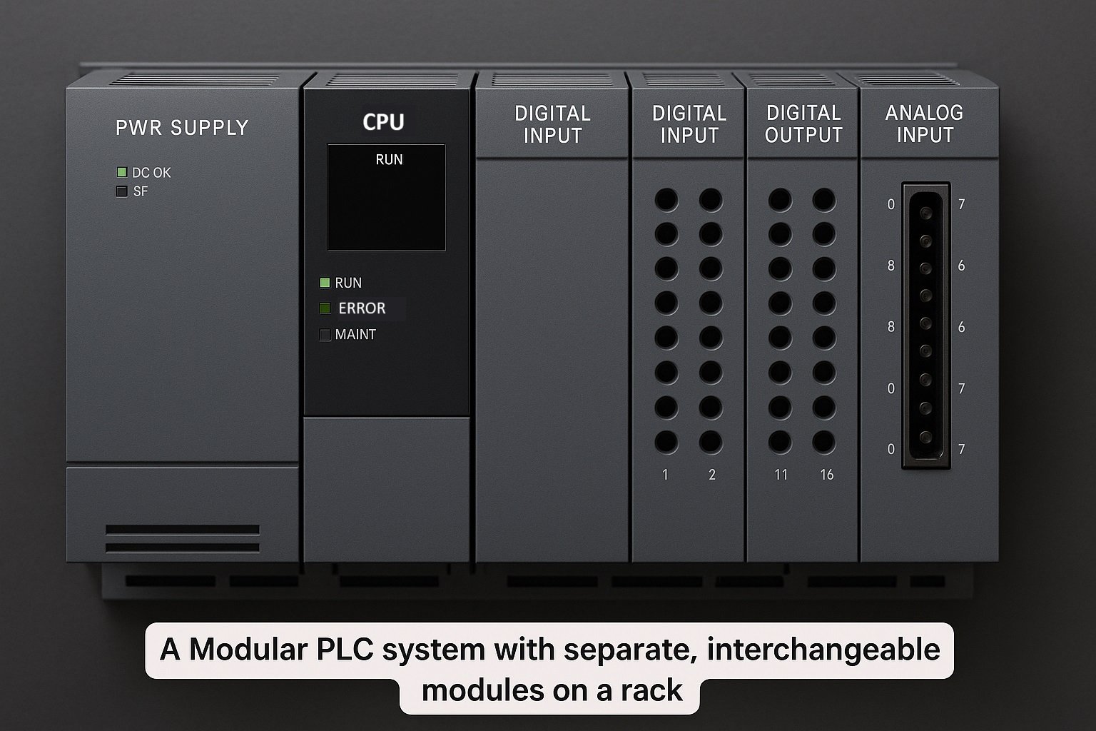
While PLCs come in various shapes and sizes, they all share a common internal architecture consisting of several key components:
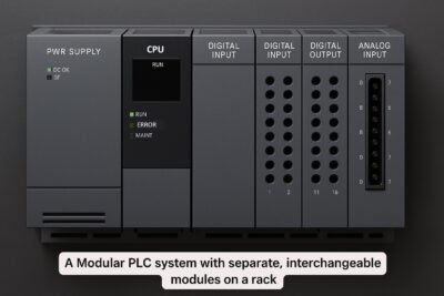
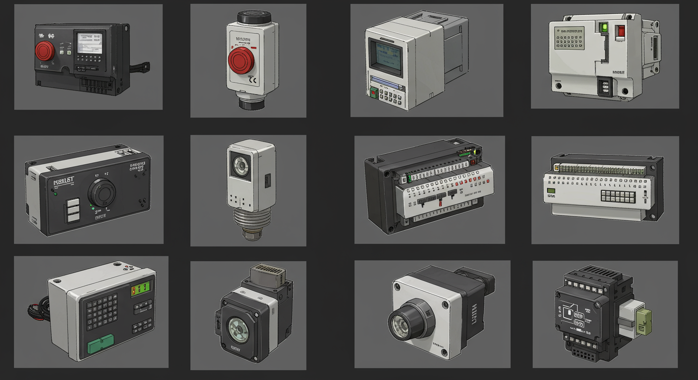
![[Image: An exploded view or clear diagram showing the main components of a modular PLC: CPU module, Power Supply module, various I/O modules (digital input, digital output, analog input) slotted into a rack/backplane. Label each component clearly with proper spellings. Caption: "Key components of a typical modular PLC system."]](https://lh7-rt.googleusercontent.com/docsz/AD_4nXfD_6qzsY3taRkH9V3FuHZ-xFFZqQuheCk19tHA2Jvf1f3Q9AeqLKn8StiX8t8GAOXTuwF_LxDV_eoZqCXzvSot0saHZkniLm0zYeJ2XYQs1wtzCAadDTT8aqGS4cc3fJjYFTkxtQ?key=thqV8XyW7_CRaxBL5v0aqQ)
- Central Processing Unit (CPU):
- The Brain: The CPU is the heart of the PLC. It’s a microprocessor that executes the control program, performs logical operations, calculations, and manages communication with other components.
- Memory Management: It reads data from inputs, accesses the stored program from memory, and writes data to outputs.
- Operating System: The CPU runs a specialized operating system (firmware) that handles tasks like program execution, I/O management, and diagnostics.
- Clock Speed: The speed of the CPU (measured in MHz or GHz) determines how quickly it can process instructions, impacting the overall scan time of the PLC.
- Memory Unit:
- Program Memory: Stores the user-written control program (the set of instructions that dictate the PLC’s behavior). This can be ROM (Read-Only Memory), EPROM (Erasable Programmable ROM), EEPROM (Electrically Erasable Programmable ROM), or Flash memory. Modern PLCs often use non-volatile RAM (like Flash or battery-backed RAM) so the program isn’t lost when power is removed.
- Data Memory: Stores information related to the state of inputs and outputs, timer and counter values, internal variables, and other data generated during program execution. This is typically volatile RAM (Random Access Memory), though critical data may be backed up.
- System Memory: Used by the CPU for the operating system and other system functions.
- Input/Output (I/O) Modules:
- The Senses and Muscles: I/O modules are the interface between the PLC’s CPU and the physical world of sensors and actuators. They convert the electrical signals from input devices into digital signals the CPU can understand, and convert the CPU’s digital signals back into electrical signals that can control output devices.
- Input Modules: Receive signals from devices like pushbuttons, limit switches, proximity sensors, temperature sensors, pressure transmitters, etc.
- Digital Input Modules: Detect discrete (ON/OFF) states.
- Analog Input Modules: Convert continuous variable signals (e.g., 4-20mA or 0-10V from a temperature sensor) into digital values.
- Output Modules: Send signals to devices like indicator lights, motor starters, solenoid valves, relays, variable frequency drives (VFDs), etc.
- Digital Output Modules: Provide discrete ON/OFF control.
- Analog Output Modules: Provide a variable output signal (e.g., to control the speed of a motor or the position of a valve).
- Isolation: I/O modules typically provide electrical isolation (often using optocouplers) between the field devices and the PLC’s internal circuitry to protect the CPU from electrical noise and voltage surges.
- Power Supply Unit:
- The Lifeline: The power supply converts the available AC or DC line voltage (e.g., 120/240V AC or 24V DC) into the various DC voltages required by the CPU, memory, and I/O modules.
- Stability and Regulation: It must provide stable, regulated, and clean power, often with built-in protection against overvoltage, undervoltage, and short circuits, to ensure reliable PLC operation in noisy industrial environments.
- Programming Device/Interface:
- The Communicator: This is the tool used to create, edit, download, and monitor the PLC program. In the early days, dedicated handheld programming terminals were common.
- Modern Approach: Today, it’s almost always a standard personal computer (PC) or laptop running specialized PLC programming software provided by the PLC manufacturer (e.g., Siemens TIA Portal, Rockwell Studio 5000, Schneider EcoStruxure Control Expert).
- Connection: The PC connects to the PLC via various communication ports like Ethernet, USB, or older serial ports (RS-232, RS-485).
- Communication Interface/Ports:
- Networking Capability: Most modern PLCs have built-in communication ports to connect to programming devices, other PLCs, HMIs (Human-Machine Interfaces), SCADA (Supervisory Control and Data Acquisition) systems, and enterprise networks.
- Protocols: Common industrial communication protocols include Ethernet/IP, Profinet, Modbus (TCP/IP and RTU), EtherCAT, DeviceNet, and Profibus.
How a PLC Operates: The Rhythmic Scan Cycle
A PLC doesn’t execute its program like a typical computer program that runs once and then stops. Instead, it operates in a continuous, repetitive loop called the scan cycle. This cycle is fundamental to the PLC’s real-time control capabilities. The PLC executes these steps very rapidly, often in milliseconds.
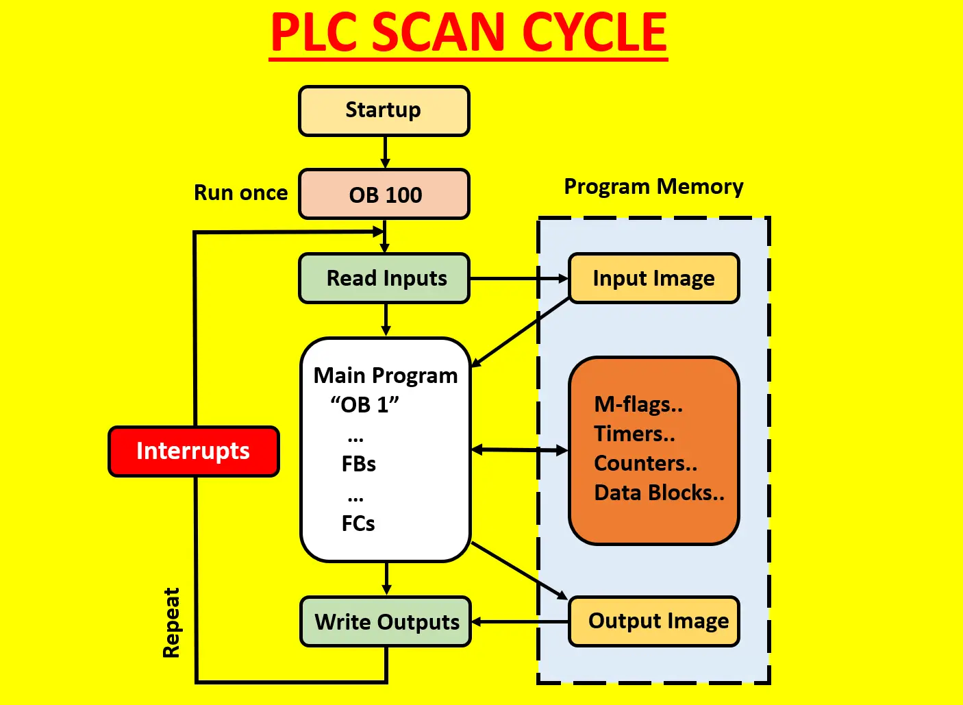
The scan cycle consists of four main phases:
- Input Scan (Read Inputs):
- The PLC reads the status of all connected physical input devices (switches, sensors, etc.) via the input modules.
- It takes a “snapshot” of these input states and stores them in an internal memory area called the Input Image Table or Process Input Image (PII). This table reflects the state of the inputs at the beginning of that specific scan cycle.
- Program Scan (Execute Logic):
- The CPU executes the user-written control program instruction by instruction, typically from top to bottom, left to right (for Ladder Logic).
- During program execution, the CPU reads the input states from the Input Image Table (not directly from the physical inputs, to ensure consistency within that scan).
- Based on the logic programmed (AND, OR, NOT, timers, counters, mathematical operations, etc.), the CPU determines the required state for the output devices.
- The results of these logical operations are written to an internal memory area called the Output Image Table or Process Output Image (PIQ). This table holds the intended states for the outputs.
- Output Scan (Write Outputs):
- After the entire program has been executed, the PLC transfers the values stored in the Output Image Table to the physical output modules.
- The output modules then energize or de-energize the connected output devices (motors, solenoids, lights, etc.), causing them to change state according to the program’s logic.
- Housekeeping and Communications (Overhead):
- During this phase, the PLC performs internal diagnostic checks to ensure its hardware and software are functioning correctly.
- It also handles communication requests, such as:
- Communicating with the programming device (e.g., uploading/downloading programs, monitoring data).
- Exchanging data with other PLCs or HMIs/SCADA systems.
- Updating internal timers and counters.
- This phase ensures the PLC remains responsive and healthy.
This entire four-step cycle repeats continuously as long as the PLC is in “Run” mode. The time it takes to complete one full scan cycle is called the scan time. Scan times are critical and vary depending on the size and complexity of the program, the number of I/O points, the speed of the CPU, and the amount of communication overhead. Typical scan times range from a few milliseconds to tens of milliseconds. For very fast processes, a shorter scan time is crucial.
Why PLCs Reign Supreme: The Undeniable Advantages
The shift from relay logic to PLCs wasn’t just an upgrade; it was a paradigm shift that brought a host of benefits, cementing the PLC’s position as the cornerstone of modern industrial automation.
- Increased Reliability:
- PLCs are solid-state devices with no moving parts like relays. This dramatically reduces mechanical failures.
- They are designed and tested to operate reliably in harsh industrial environments with temperature extremes, vibration, dust, and electrical noise.
- Greater Flexibility and Reprogrammability:
- Changing control logic is as simple as modifying the software program on a PC and downloading it to the PLC. No physical rewiring is needed. This drastically reduces downtime and costs associated with process changes or upgrades.
- Cost-Effectiveness:
- While the initial cost of a PLC might be higher than a few relays for very simple applications, for moderately complex systems, PLCs are far more economical.
- Savings come from reduced wiring, smaller panel sizes, easier troubleshooting, lower maintenance, and reduced downtime.
- Higher Processing Speed:
- PLCs execute logic much faster than relay systems can physically switch, allowing for control of faster and more complex processes. Scan times in milliseconds enable real-time responsiveness.
- Advanced Control Capabilities:
- PLCs can perform complex mathematical calculations, data manipulation, and implement sophisticated control algorithms (like PID control) that are impossible or impractical with relay logic.
- They incorporate timers, counters, sequencers, and other advanced functions as software elements.
- Ease of Troubleshooting and Diagnostics:
- PLC programming software offers powerful diagnostic tools. Maintenance personnel can monitor the program execution in real-time, observe the status of inputs, outputs, and internal variables, and quickly identify faults.
- Many PLCs have built-in diagnostics that can indicate hardware failures or program errors.
- Networking and Communication:
- Modern PLCs are designed to communicate with other PLCs, HMIs, SCADA systems, databases, and even enterprise-level systems using various industrial network protocols. This enables distributed control, data collection, and remote monitoring.
- Compact Size:
- A single PLC can replace hundreds of relays, significantly reducing the size of control panels and saving valuable factory floor space.
- Documentation:
- PLC programs can be easily documented, printed, and backed up. Changes can be tracked, making maintenance and understanding the system much simpler.
- Security (Basic and Evolving):
- PLCs offer password protection and other features to prevent unauthorized access or modifications to the control program, which is crucial for safety and operational integrity. Cybersecurity for PLCs is an increasingly important and evolving field.
Know Your Controller: Types of PLCs
PLCs are not a one-size-fits-all solution. They come in various forms to cater to different application scales and complexities:
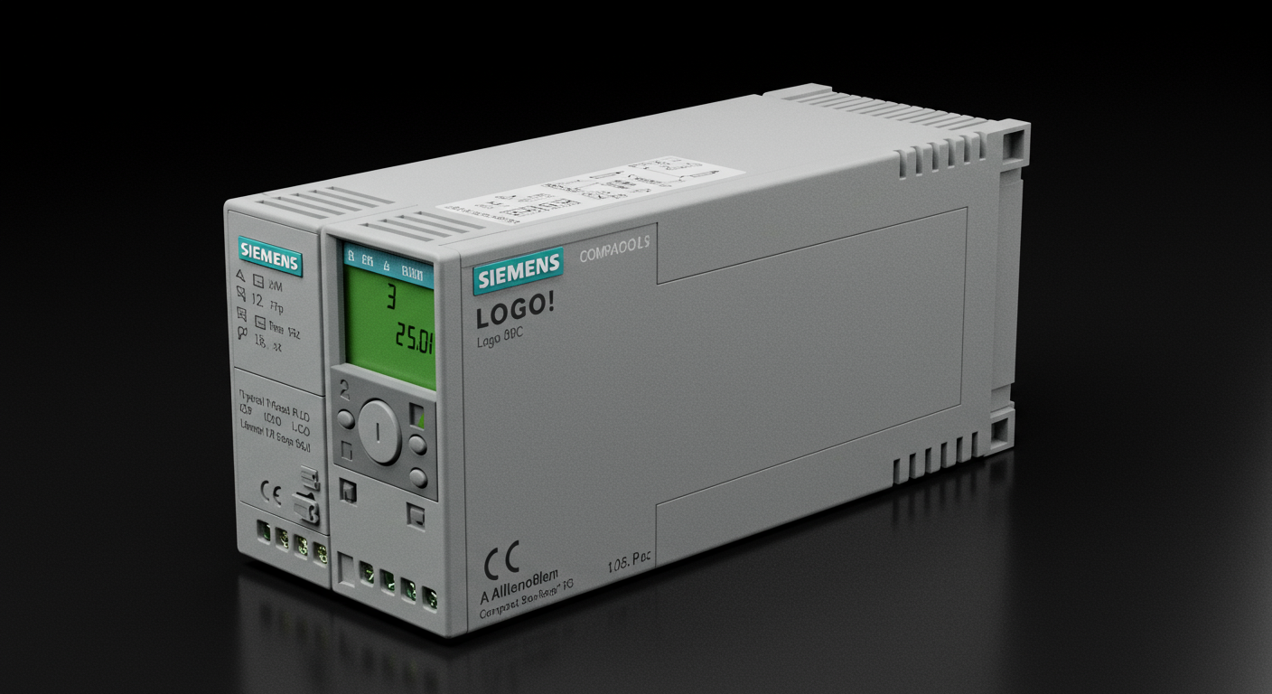
- Compact (or Micro/Nano) PLCs:

- Description: These are small, self-contained units where the processor, power supply, and a fixed number of I/O points (typically ranging from a dozen to a few dozen) are integrated into a single housing.
- Characteristics:
- Limited I/O capacity (though some allow for a small number of expansion modules).
- Lower cost.
- Simpler programming, often suited for basic control tasks.
- Less memory and processing power compared to larger PLCs.
- Applications: Small machine control, simple automation tasks, standalone equipment, replacing small relay logic systems. Examples: conveyor control, pump control, lighting control.
- Modular PLCs:

- Description: These PLCs consist of separate modules for the CPU, power supply, and various types of I/O, all mounted on a common chassis or rack with a backplane for inter-module communication.
- Characteristics:
- Highly flexible and scalable: Users can choose and combine modules to precisely match the application’s I/O requirements.
- Larger I/O capacity (hundreds or even thousands of points).
- More powerful processors and larger memory.
- Advanced features like sophisticated communication protocols, redundancy, and motion control.
- Higher cost but suitable for complex and large-scale automation.
- Applications: Large manufacturing lines, process control plants, complex machinery, building automation systems.
- Rack-Mounted PLCs:
- This is often synonymous with modular PLCs, as modular components are typically mounted on a rack. The rack provides physical support and a backplane (a circuit board with connectors) that allows the modules to communicate with each other and the CPU.
- Some very large systems might use multiple racks connected together.
- Software-Based PLCs / PC-Based Control:
- Description: This approach uses a standard industrial PC (IPC) or even a regular PC running specialized software that emulates PLC functionality. The PC is equipped with I/O cards to interface with field devices.
- Characteristics:
- Leverages the processing power, memory, and networking capabilities of modern PCs.
- Can integrate PLC control with other PC-based applications (e.g., HMI, data logging, advanced analytics) on a single platform.
- May require a real-time operating system (RTOS) extension for deterministic performance.
- Concerns sometimes arise regarding the robustness and reliability of standard PC hardware in harsh industrial environments compared to dedicated PLC hardware, though industrial PCs (IPCs) are designed to be more rugged.
- Applications: Complex applications requiring significant data processing, vision systems, or tight integration with PC-based software.
The choice between these types depends heavily on the specific application’s requirements, budget, and future scalability needs.
The Language of Automation: PLC Programming Explained
A PLC is only as smart as the program it runs. PLC programming is the process of creating the set of instructions that tell the PLC how to react to input signals and control output devices. Over the years, several programming languages have been developed, with the IEC 61131-3 standard being a key international standard that defines five common PLC programming languages. This standardization promotes interoperability and makes it easier for programmers to work with PLCs from different manufacturers.
Here are the primary PLC programming languages:
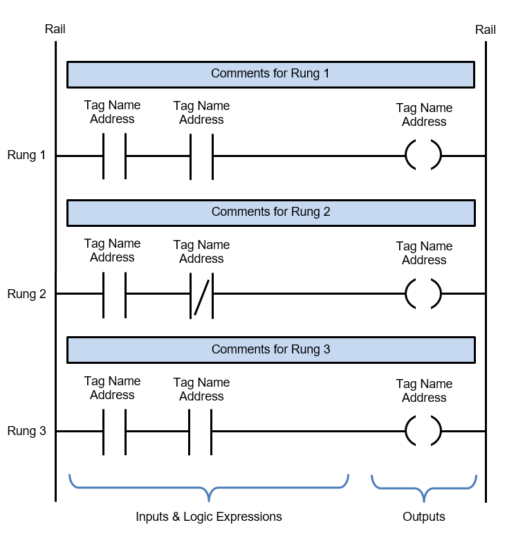
- Ladder Logic (LD):

- Description: The most widely used PLC programming language, especially in North America. It’s a graphical language that visually resembles the relay logic schematics it was designed to replace.
- Structure: Programs are organized into “rungs,” much like rungs on a ladder. Each rung represents a logical statement.
- Contacts: Represent input conditions (e.g., sensors, pushbuttons). They can be “Normally Open” (XIC – Examine If Closed) or “Normally Closed” (XIO – Examine If Open).
- Coils: Represent outputs (e.g., motors, lights, internal relays). They are energized or de-energized based on the logical continuity of the rung.
- Logic: Rungs are evaluated from left to right, top to bottom. If a path of “true” input conditions exists from the left power rail to an output coil, the coil is energized.
- Pros: Intuitive for electricians and technicians familiar with relay logic, easy to learn for simple tasks, good for discrete logic.
- Cons: Can become cumbersome for complex sequencing, mathematical operations, or data handling.
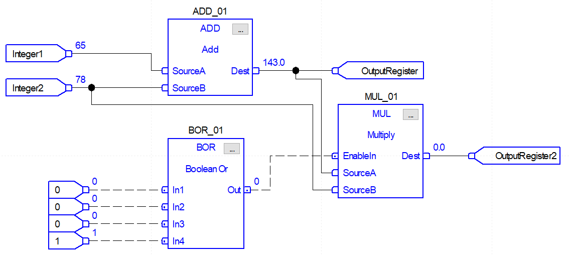
- Function Block Diagram (FBD):

- Description: Another graphical language that represents functions as blocks. These blocks have inputs and outputs, and they are “wired” together to create the control logic.
- Structure: Uses pre-defined or user-created blocks for common operations (e.g., logic gates like AND/OR, timers, counters, mathematical functions, PID controllers).
- Pros: Good for visualizing signal flow, well-suited for process control applications, can simplify complex logic by encapsulating it within blocks.
- Cons: Can become visually cluttered for very large programs if not well-structured.
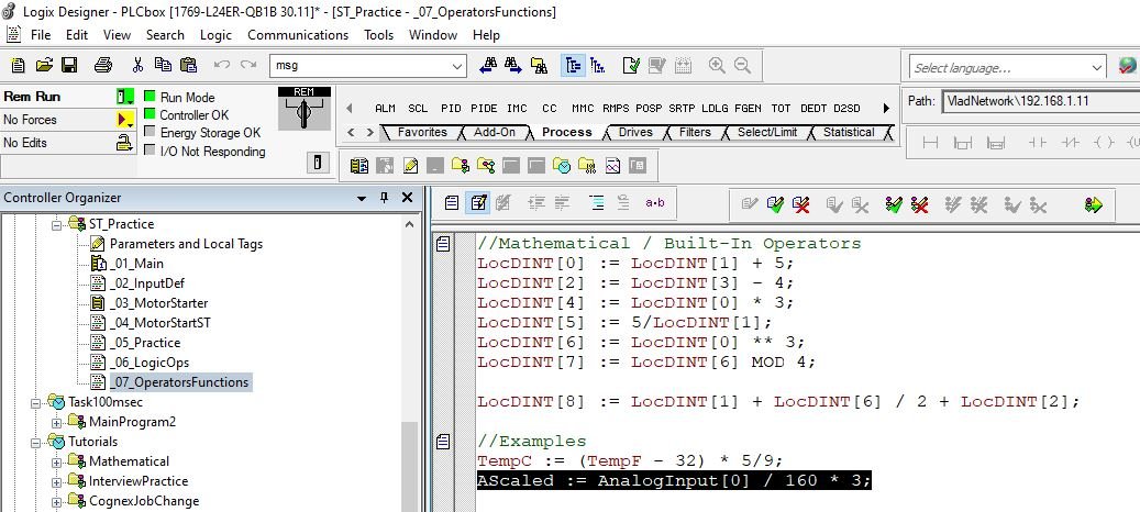
- Structured Text (ST):
- Description: A high-level, text-based programming language similar in syntax to PASCAL or C.
- Structure: Uses statements, loops (FOR, WHILE), conditional execution (IF-THEN-ELSE, CASE), and functions to define the control logic.
- Pros: Excellent for complex mathematical calculations, string manipulation, data handling, and implementing complex algorithms. More compact for certain types of logic than graphical languages. Easier for programmers with a background in traditional IT programming.
- Cons: Steeper learning curve for those unfamiliar with text-based programming. Can be less intuitive for visualizing simple discrete logic compared to LD.
- Instruction List (IL):
- Description: A low-level, text-based language that resembles assembly language. It uses mnemonic codes to represent instructions (e.g., LD for Load, ST for Store, AND, OR).
- Structure: Consists of a sequence of instructions, each operating on an accumulator or registers.
- Pros: Can be very efficient in terms of memory usage and execution speed. Useful for optimizing performance-critical sections of code.
- Cons: Difficult to read, write, and debug compared to other languages. Prone to errors. Its use is declining in favor of ST for complex tasks and graphical languages for simpler logic. Many modern PLC platforms are phasing out or limiting support for IL.
- Sequential Function Chart (SFC):

- Description: A graphical language designed for programming sequential control operations. It’s based on the Grafcet standard.
- Structure: Organizes the program into a series of steps and transitions.
- Steps: Represent states in the process. Actions (e.g., turn on a motor) are associated with each active step.
- Transitions: Represent the conditions that must be met to move from one step to the next.
- Flow: Allows for sequential, parallel, and alternative sequences.
- Pros: Excellent for managing complex sequences and processes with distinct operational states (e.g., batch processes, machine cycles). Provides a clear, high-level overview of the control flow. Can embed actions written in other IEC languages (like LD or ST) within its steps.
- Cons: Not ideal for all types of logic; best used as an organizational tool for sequential parts of a program.
Most PLC programming software allows developers to use multiple languages within the same project, choosing the best language for each specific task. For example, SFC might be used to manage the overall sequence, with individual steps and actions programmed in LD or ST.
PLC Inputs and Outputs (I/O) in Depth: The PLC’s Connection to Reality
The I/O system is the PLC’s bridge to the physical world. Understanding the different types of inputs and outputs is crucial for designing and implementing effective automation systems.
- Digital (Discrete) Inputs:
* Function: Detects an ON/OFF, True/False, or High/Low state.
* Examples:
* Pushbuttons (start/stop)
* Selector switches
* Limit switches (detecting presence or position of an object)
* Proximity sensors (inductive for metal, capacitive for other materials)
* Photoelectric sensors (detecting presence by light beam interruption)
* Level switches (float switches indicating high/low liquid level)
* Relay contacts (from other control circuits)
* Signal Type: Typically a voltage level (e.g., 24V DC, 120V AC) indicates an ON state, and 0V indicates an OFF state.
- Digital (Discrete) Outputs:
* Function: Provide an ON/OFF signal to control an external device.
* Examples:
* Indicator lights / Pilot lamps
* Solenoid valves (controlling air or fluid flow)
* Relays and Contactors (to switch higher power loads like motors)
* Small motors (directly, if current/voltage is low enough)
* Alarms and Horns
* Signal Type: The PLC output module switches a voltage (e.g., 24V DC, 120V AC) to the connected device. Outputs can be relay type (using physical relay contacts, good for AC or higher currents), transistor type (faster, for DC loads), or triac type (for AC loads).
- Analog Inputs:
* Function: Measure continuous, variable physical quantities. The PLC’s analog input module converts these varying signals into digital values that the CPU can process (using an Analog-to-Digital Converter, or ADC).
* Examples:
* Temperature sensors (Thermocouples, RTDs – Resistance Temperature Detectors, often requiring signal conditioners)
* Pressure transmitters
* Level transmitters (ultrasonic, radar, hydrostatic)
* Flow meters
* Potentiometers (measuring position)
* Load cells (measuring weight/force)
* Humidity sensors
* Signal Type: Common analog signals include:
* Voltage: 0-10V DC, 0-5V DC, +/- 10V DC
* Current: 4-20mA (most common in industry due to its noise immunity and ability to detect broken wires – 0mA indicates a fault), 0-20mA.
* Resolution: The precision of an analog input is determined by its resolution (e.g., 12-bit, 16-bit). A 12-bit ADC can represent 2^12 = 4096 discrete steps.
- Analog Outputs:
* Function: Provide a continuously variable control signal to an external device. The PLC’s analog output module converts a digital value from the CPU into an analog electrical signal (using a Digital-to-Analog Converter, or DAC).
* Examples:
* Proportional valves (controlling flow rate precisely)
* Variable Frequency Drives (VFDs) / Variable Speed Drives (VSDs) to control motor speed
* Actuators requiring variable positioning (e.g., dampers)
* Chart recorders or analog meters (less common now)
* Signal Type: Similar to analog inputs: 0-10V DC, 4-20mA.
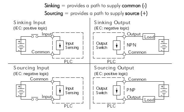
- Sourcing vs. Sinking I/O (Mainly for DC Digital I/O):
This concept describes the direction of current flow between the I/O module and the field device. It’s crucial for correct wiring.
* Sourcing (PNP): A sourcing I/O module provides (sources) the current to the field device.
* Sourcing Input Module: Expects current to flow from the input device into the input terminal. The input device connects the positive supply to the PLC input terminal.
* Sourcing Output Module: The output terminal provides the positive voltage. The field device is connected between the output terminal and common (0V). When ON, current flows out of the module to the device.
* Sinking (NPN): A sinking I/O module receives (sinks) current from the field device.
* Sinking Input Module: Expects current to flow out of the input terminal to the input device (which connects the terminal to common/0V). The input device connects the PLC input terminal to the negative supply (common).
* Sinking Output Module: The output terminal provides a path to common (0V). The field device is connected between a positive voltage source and the output terminal. When ON, current flows from the device into the module.
* Compatibility: It’s important to match the type of I/O module (sourcing/sinking) with the type of sensor or actuator (PNP/NPN for sensors). Mismatches can lead to non-functional or damaged components.
Specialty I/O Modules:
Beyond standard digital and analog I/O, PLCs often support specialized modules for specific tasks:
* High-Speed Counter (HSC) Modules: For counting pulses from encoders or flow meters at rates faster than the PLC scan can normally handle. Used in positioning, speed measurement, and totalizing applications.
* Temperature Input Modules (RTD/Thermocouple): Dedicated modules designed to directly interface with RTDs or thermocouples, often including built-in signal conditioning and cold-junction compensation (for thermocouples).
* Motion Control Modules: For precise control of servo motors or stepper motors in applications like robotics, CNC machines, and packaging equipment. These modules can handle complex motion profiles, synchronization, and feedback.
* Communication Modules: To add specific network capabilities (e.g., Profibus, DeviceNet, Ethernet/IP, Modbus) if not built into the CPU.
* PID Modules: Some PLCs offer dedicated modules for Proportional-Integral-Derivative (PID) control loops, offloading this processing from the main CPU for critical loops.
* Weight/Strain Gauge Modules: For direct connection to load cells.
Where are PLCs Used? The Unsung Heroes of Modern Life
The versatility and robustness of PLCs have made them indispensable in an astonishingly wide array of industries and applications. You might be surprised by how many aspects of modern life are touched by these controllers.
- Manufacturing:
- Assembly Lines: Controlling robots, conveyors, presses, and sequencing operations in automotive, electronics, and consumer goods manufacturing.
- Material Handling: Managing automated guided vehicles (AGVs), sorters, stacker cranes in warehouses and distribution centers.
- CNC Machining: While CNC controllers are specialized, PLCs often manage auxiliary functions like coolant systems, tool changers, and part loading/unloading.
- Packaging: Controlling filling, capping, labeling, and palletizing machines.
- Process Control Industries:
- Oil & Gas: Monitoring and controlling wellheads, pipelines, refineries, and processing plants.
- Chemical Processing: Managing reactors, mixers, temperature, pressure, and flow control for precise chemical production.
- Water and Wastewater Treatment: Controlling pumps, valves, chemical dosing, filtration systems, and monitoring water quality.
- Food and Beverage: Automating mixing, cooking, bottling, packaging, and Clean-In-Place (CIP) systems, ensuring consistency and hygiene.
- Pharmaceuticals: Strict control of batch processes, environmental conditions, and documentation in drug manufacturing.
- Building Automation / Smart Buildings:
- HVAC (Heating, Ventilation, and Air Conditioning): Optimizing temperature, humidity, and air quality for comfort and energy efficiency.
- Lighting Control: Automated lighting schedules, occupancy-based lighting.
- Security and Access Control Systems: Integrating sensors, alarms, and access points.
- Elevator and Escalator Control: Managing movement, safety interlocks, and floor selection.
- Power Generation and Distribution:
- Power Plant Control: Monitoring and controlling turbines, boilers, generators, and auxiliary systems.
- Substation Automation: Controlling circuit breakers, transformers, and monitoring grid parameters.
- Renewable Energy: Managing wind turbines (pitch control, yaw control), solar panel tracking, and power conversion.
- Transportation:
- Traffic Light Control Systems: Optimizing traffic flow at intersections.
- Railway Systems: Signaling, track switching, and monitoring.
- Tunnel Ventilation and Safety Systems.
- Baggage Handling Systems in airports.
- Agriculture (Smart Farming):
- Automated irrigation systems.
- Climate control in greenhouses.
- Automated feeding systems for livestock.
- Entertainment:
- Amusement park rides: Controlling motion, safety interlocks, and special effects.
- Stage automation in theaters: Moving scenery, lighting, and effects.
This list is by no means exhaustive. Essentially, anywhere there’s a need for reliable, automated control of machinery or processes, you’re likely to find a PLC at work.
Choosing the Right PLC: Key Considerations
Selecting the appropriate PLC for a specific application is a critical decision that impacts performance, cost, and future scalability. Here are key factors to consider:
- I/O Requirements (Number and Type):
- How many digital inputs/outputs are needed?
- How many analog inputs/outputs are needed?
- Are there any special I/O requirements (high-speed counters, temperature, motion)?
- Always plan for future expansion – typically add 20-25% spare I/O capacity.
- Memory Capacity:
- The size and complexity of the control program will determine the amount of program memory needed.
- Data logging or complex calculations will require sufficient data memory.
- Processing Speed (Scan Time):
- For high-speed applications, a PLC with a fast CPU and low scan time is essential.
- Consider the complexity of the logic and the number of I/O points, as these affect scan time.
- Communication Needs:
- What devices does the PLC need to communicate with (HMIs, SCADA, other PLCs, drives, enterprise systems)?
- What communication protocols are required (Ethernet/IP, Profinet, Modbus, etc.)?
- Are remote access or cloud connectivity features needed?
- Programming Software and Languages:
- Is the programming software intuitive and user-friendly?
- Does it support the programming languages your team is familiar with or best suited for the application?
- Consider the cost of software licenses and training.
- Operating Environment:
- What are the ambient temperature, humidity, vibration, and electrical noise levels where the PLC will be installed?
- Choose a PLC rated for the specific environmental conditions. Some applications may require PLCs with extended temperature ranges or special enclosures.
- Scalability and Modularity:
- Can the PLC system be easily expanded if the application grows or requirements change?
- Modular PLCs offer better scalability than compact PLCs.
- Vendor Support, Reliability, and Familiarity:
- What is the reputation of the PLC manufacturer for reliability and support?
- Is local technical support and training available?
- If your facility already uses a particular brand of PLC, standardizing can simplify maintenance, spare parts inventory, and programming.
- Cost:
- Consider the total cost of ownership, including hardware, software, development time, training, and maintenance, not just the initial purchase price.
- Security Features:
- What security features are offered to protect against unauthorized access and cyber threats? (e.g., password protection, encrypted communications, role-based access).
A thorough analysis of these factors will help in selecting a PLC that meets current needs and provides a solid foundation for future automation endeavors.
The Evolution and Future of PLCs: Smarter, Faster, More Connected
PLCs have come a long way since their inception as relay replacers. Their evolution continues, driven by advancements in microprocessor technology, software, and the ever-increasing demands of modern industry.

Key Trends Shaping the Future of PLCs:
- Integration with IIoT (Industrial Internet of Things) & Industry 4.0:
- PLCs are becoming key data sources and control points within IIoT ecosystems.
- Enhanced connectivity (especially via Ethernet and wireless protocols like OPC UA) allows PLCs to share data seamlessly with higher-level systems (MES, ERP, cloud platforms) for analytics, predictive maintenance, and optimized decision-making.
- This enables “smart factories” where machines and systems communicate and cooperate.
- Enhanced Cybersecurity:
- As PLCs become more connected, they also become more vulnerable to cyber threats.
- Manufacturers are focusing on incorporating more robust security features like encrypted communication, secure boot, user authentication, role-based access control, and intrusion detection systems.
- Adherence to industrial cybersecurity standards (e.g., IEC 62443) is becoming increasingly important.
- Edge Computing Capabilities:
- Some modern PLCs and PACs are incorporating edge computing capabilities. This means they can perform more data processing, analytics, and decision-making locally, at the machine or process level, rather than sending all data to the cloud.
- This reduces latency, saves bandwidth, and allows for faster responses in critical applications.
- PACs (Programmable Automation Controllers):
- PACs are often seen as an evolution of PLCs, or a higher-end category. They combine PLC ruggedness and reliability with PC-like processing power, memory, and networking capabilities.
- PACs typically excel in applications requiring:
- Multi-domain control (logic, motion, process control on a single platform).
- Extensive data handling and logging.
- Open architectures and standard programming languages (like C/C++ in addition to IEC 61131-3 languages).
- Advanced communication and enterprise integration.
- The line between high-end PLCs and PACs is often blurry.
- AI and Machine Learning (ML) Integration:
- The future will see tighter integration of AI/ML capabilities with PLC systems.
- This could involve PLCs executing AI models locally (on edge devices) for tasks like predictive maintenance (analyzing sensor data to predict failures), quality control (using vision data), or process optimization.
- PLCs will also provide the critical data needed to train these AI models.
- Simplified Programming and Configuration:
- While PLCs are becoming more powerful, there’s also a drive to make them easier to program and configure, especially for common tasks.
- This includes more intuitive software, auto-configuration tools, and potentially low-code/no-code programming environments for simpler applications.
- Increased Use of Standard IT Technologies:
- PLCs are increasingly adopting standard IT technologies like Ethernet, TCP/IP, OPC UA, and even web-based interfaces for configuration and monitoring. This facilitates integration and leverages existing IT infrastructure and expertise.
The PLC is not a static technology; it is constantly adapting and evolving to meet the challenges and opportunities of the digital age in industry.
Getting Started with PLCs: Your Journey into Automation
If this deep dive has sparked your interest in learning more about PLCs and perhaps even programming them, here are some resources and pathways to get started:
- Online Courses and Tutorials:
- Platforms like Udemy, Coursera, YouTube, and dedicated automation training websites (e.g., AutomationDirect, RealPars) offer numerous courses ranging from beginner to advanced levels.
- Look for courses that cover PLC fundamentals, specific vendor platforms (Siemens, Allen-Bradley, etc.), and programming languages like Ladder Logic.
- Vendor Training Programs:
- Major PLC manufacturers (Siemens, Rockwell Automation, Schneider Electric, Mitsubishi Electric, Omron, etc.) offer certified training courses, both online and in-person. These are excellent for in-depth knowledge of their specific hardware and software.
- PLC Simulators and Software:
- Many PLC vendors provide simulation software that allows you to write, test, and debug PLC programs without needing physical hardware. This is a cost-effective way to practice.
- Some vendors offer free or trial versions of their programming environments.
- Hands-On Kits and Trainers:
- For practical experience, consider purchasing a PLC trainer kit or a small, inexpensive PLC (like a micro PLC). These kits often come with basic I/O components (switches, lights) to practice wiring and programming.
- Books and Manuals:
- There are many excellent textbooks on PLC theory and programming. Additionally, vendor documentation and manuals are invaluable resources.
- Join Online Communities and Forums:
- Websites like PLCS.net, Reddit (r/PLC), and LinkedIn groups dedicated to automation are great places to ask questions, share knowledge, and learn from experienced professionals.
Learning PLCs requires a blend of theoretical understanding and practical application. Start with the basics, be patient, and practice regularly.
Conclusion: The Enduring Power of the PLC
From its humble beginnings as an electronic replacement for cumbersome relay panels, the Programmable Logic Controller has evolved into a sophisticated and indispensable cornerstone of modern industrial automation. Its ruggedness, flexibility, and ever-expanding capabilities have empowered industries worldwide to achieve unprecedented levels of efficiency, productivity, safety, and quality.
The PLC is more than just a controller; it’s an enabler of innovation. It bridges the gap between human ingenuity and mechanical execution, translating complex ideas into tangible, automated actions. As we move further into the era of Industry 4.0, IIoT, and AI-driven manufacturing, the PLC will continue to play a central role, adapting and integrating with new technologies to push the boundaries of what’s possible.
Understanding the “What, Why, and How” of PLCs is no longer just for automation engineers; it’s becoming increasingly relevant for anyone involved in manufacturing, industrial operations, or technology. These unseen brains are quietly, reliably, and powerfully shaping the world around us, one scan cycle at a time.


